

- Stock: In Stock
- Model: DOEPFER-A-132-8
More from this brand
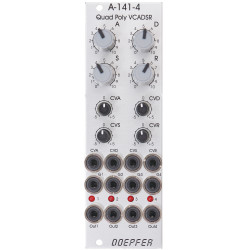
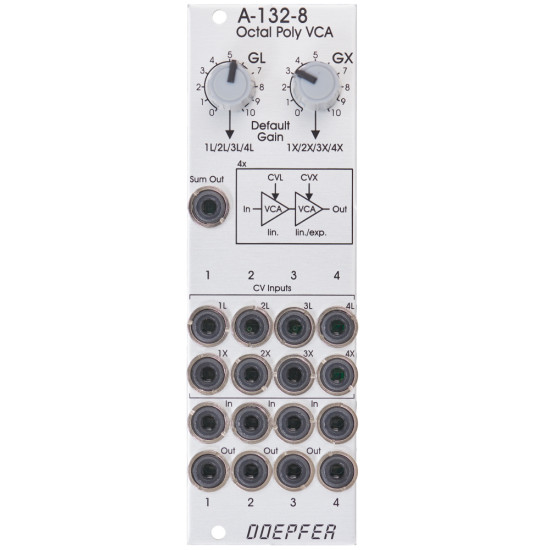
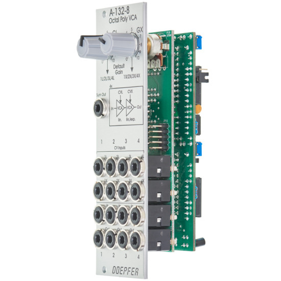
A-132-8 is an octal VCA and primarily planned for polyphonic applications. The module contains four VCA pairs. The amplification range for each VCA is 0 ... 1. 0V CV corresponds to amplification 0 (full suppression), +10V CV to amplification 1. Each pair includes two daisy-chained VCAs. One VCA has a linear control scale, for the second VCA linear or exponential control scale can be chosen by means of jumpers. We decided to provide two VCAs for each voice because usually one VCA is required for loudness envelope and a second one for velocity (or other functions like individual voltage-controlled loudness of each voice, amplitude modulation and so on). All VCAs are DC coupled and can be used in special applications also for the processing of control voltages.
hese controls and in/outputs are available:
The module features two Default Gain controls (GL, GX), that enable the opening of the first four VCAs (L) and/or second four VCAs (X). For this the controls GL and GX generate two internal control voltages 0...+10V which are connected to the switching contacts of the sockets 1L...4L (control GL) and 1X...4X (control GX). As long as no patch cable is inserted into the socket in question the internal default control voltage (GL or GX) is used to control the corresponding VCA. This is necessary when the VCA in question is not in use (i.e. no external CV available). Otherwise the VCA would close and there would be no output signal even if the other VCA in the chain is open. The controls GL and GX are also useful for testing polyphonic patches (e.g. for tuning the VCOs). Factory settings: Application: The following document shows the positions and functions of the jumpers and trimming potentiometers of the module: A132_8_trimming_potentiometers_and_jumpers.pdf | ||
Breite/Width: 8 TE / 8 HP / 40.3 mm
Tiefe/Depth: 45 mm (gemessen ab der Rückseite der Frontplatte / measured from the rear side of the front panel)
Strombedarf/Current: +40mA (+12V) / -40mA (-12V)
-285x169.png)
